Assembly#
This page walks through assembling a RoSHI body tracker: the SlimeVR Hyperion PCB, a BNO085 IMU, and a custom 3D-printed case sized for rigid AprilTag mounting. All STEP/STL files, firmware, and Python tools live in the RoSHI-Hardware repo; after the mechanical build, flash firmware per Software (firmware and host tools).
Tip
Soldering rule used throughout this page: every through-hole joint should be shiny, complete, and fully fill the barrel—when you flip the board, each pad should show a filled annulus, not a dry hole.
3D printing#
Printed parts (tracker case, receiver enclosure, strap hardware) live under
RoSHI-Hardware → 3D Prints/
(see repo):
Design/— CAD sources (STEP and design files).Print/— STL files ready for slicing.
We print in PLA matte; other materials (e.g. PETG) usually need slicer or CAD tolerance tweaks. The internal spacing is a firm press fit so the IMU stack does not rattle during motion.
PCB source and ordering#
We use the PCB from the SlimeVR Hyperion Multi-IMU BMI BNO project (Case guide on GitHub); follow its Gerber / JLCPCB ordering notes and recommended board thickness.
IMU choice. We use the BNO085 for its on-board sensor fusion—orientation is ready to use with no extra MCU code. A lower-cost ICM-45686 + QMC6309 build works on the same PCB family but requires custom fusion code on the ESP8266 WeMos D1 Mini.
Why a custom case? RoSHI’s calibration relies on a rigidly mounted AprilTag on a known face of the enclosure—the stock Hyperion case has no such feature. Any SlimeVR-class board / IMU is fine in principle, but you must adapt the case (strap mounts, clearance, tag plane) to that PCB outline. See Attaching AprilTags below for tag spec and orientation.
Tracker assembly#
The photos below follow one build order: charging board first, then passives and connectors, then the IMU and MCU, then test and switch, then the enclosure stack.
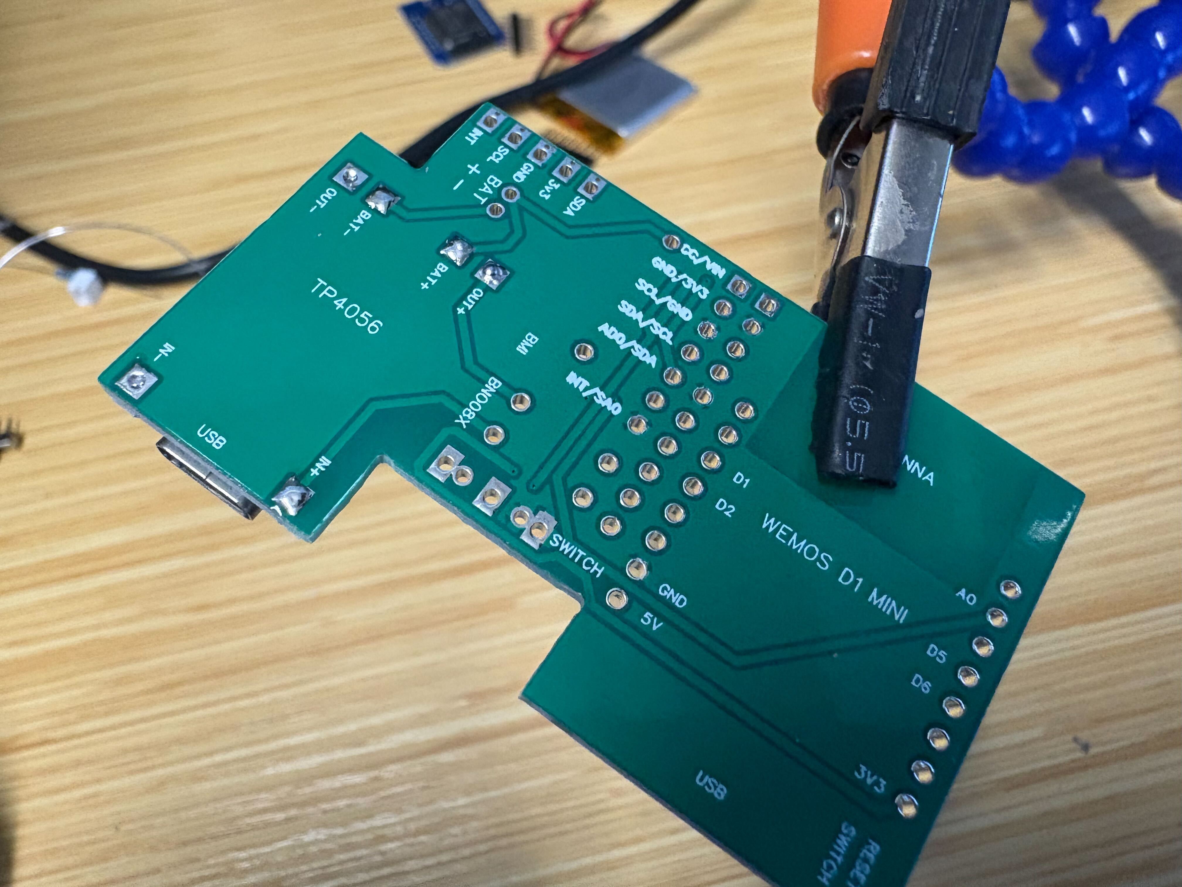
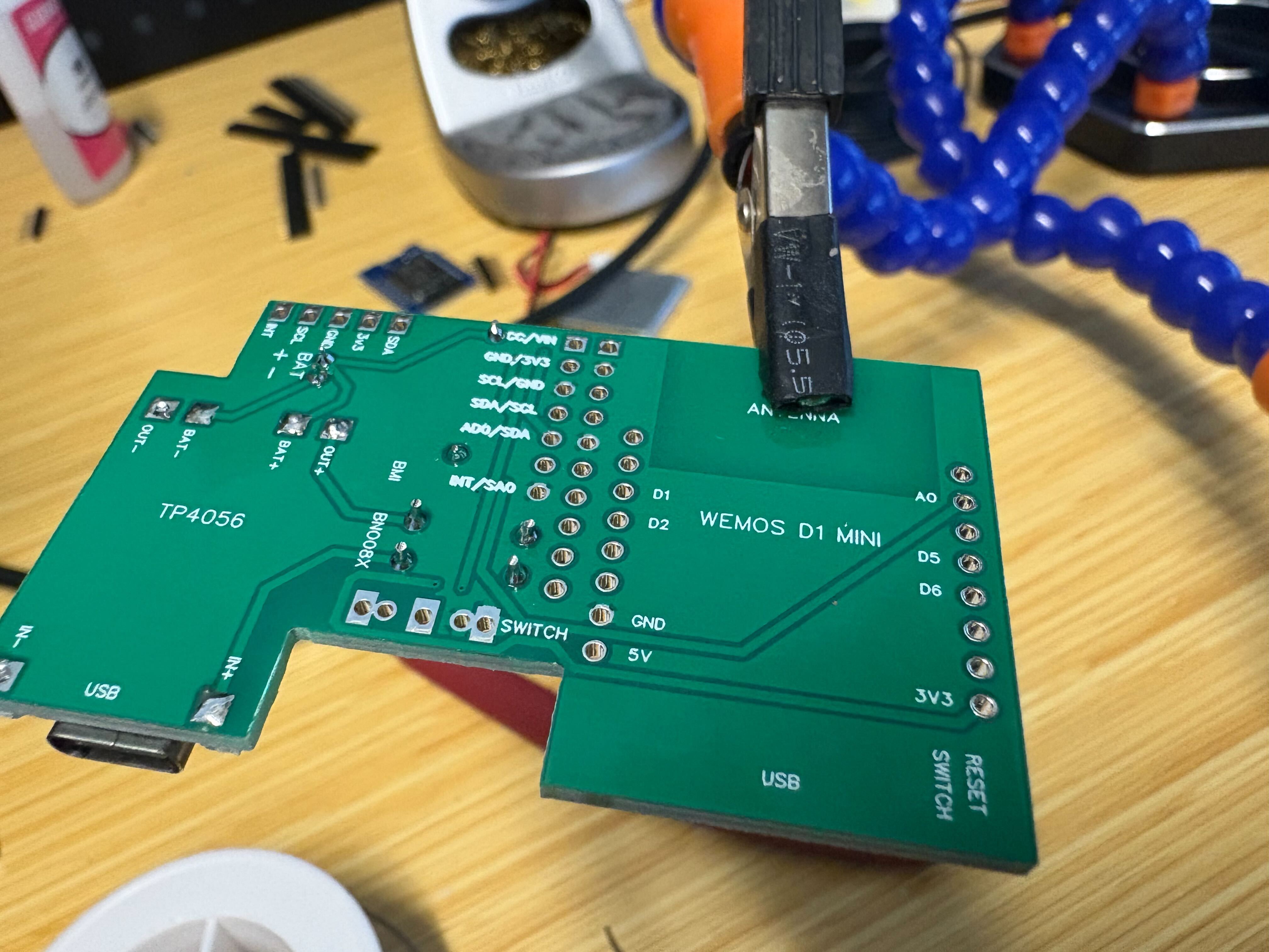
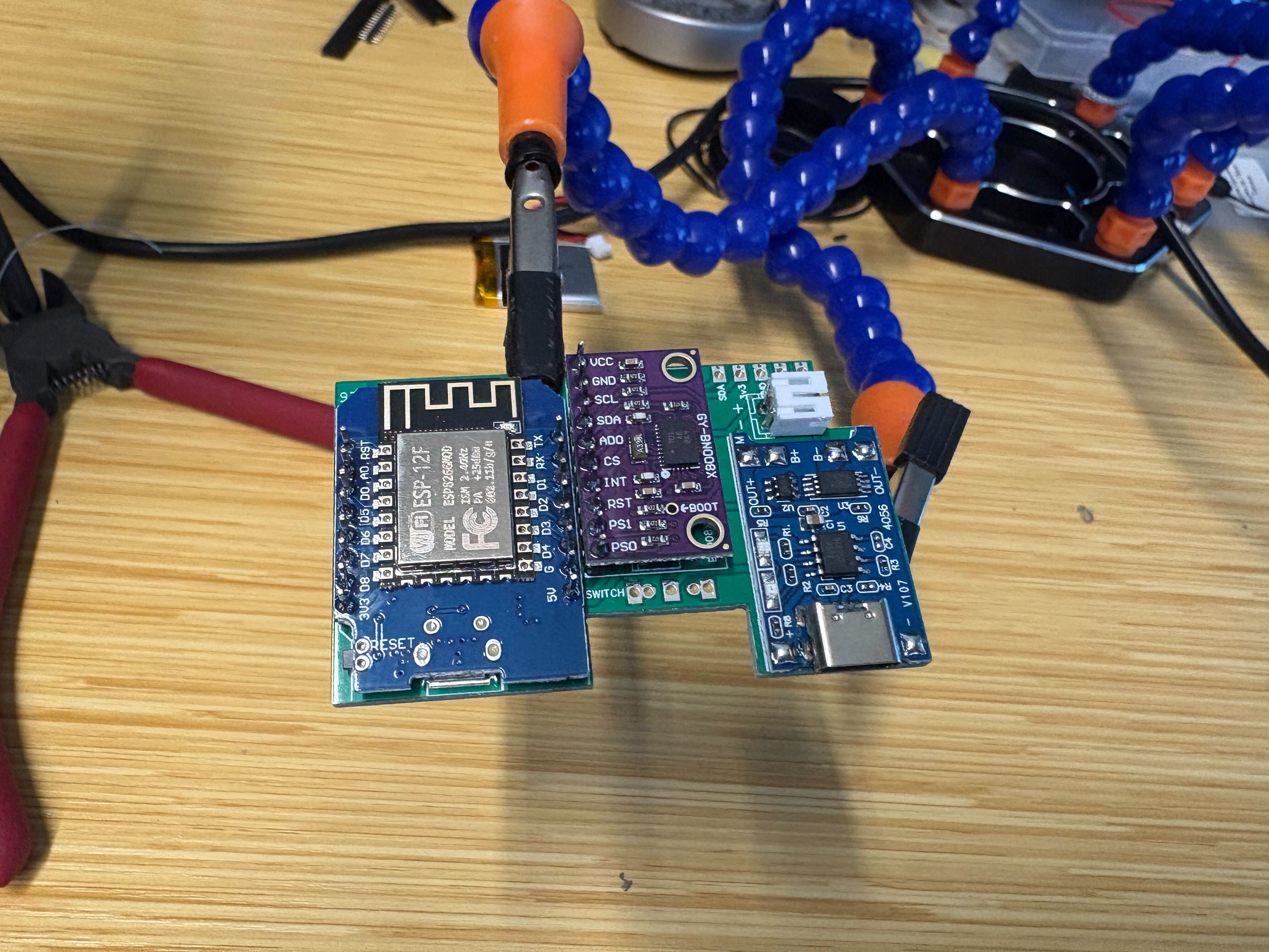
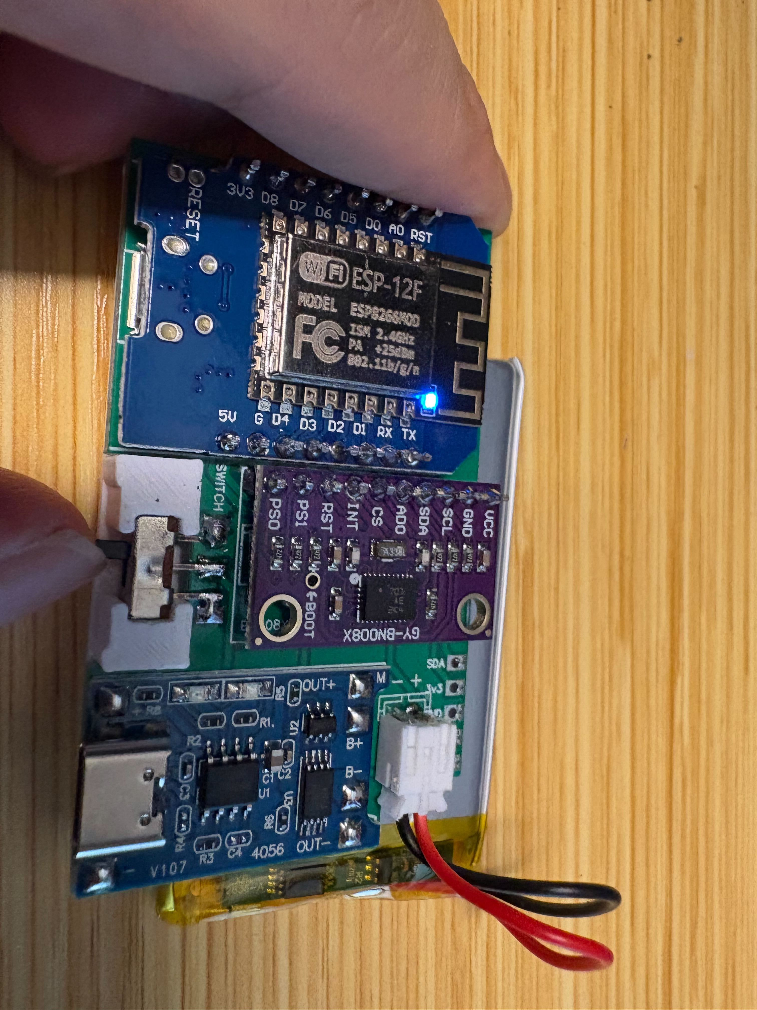
Parts layout#
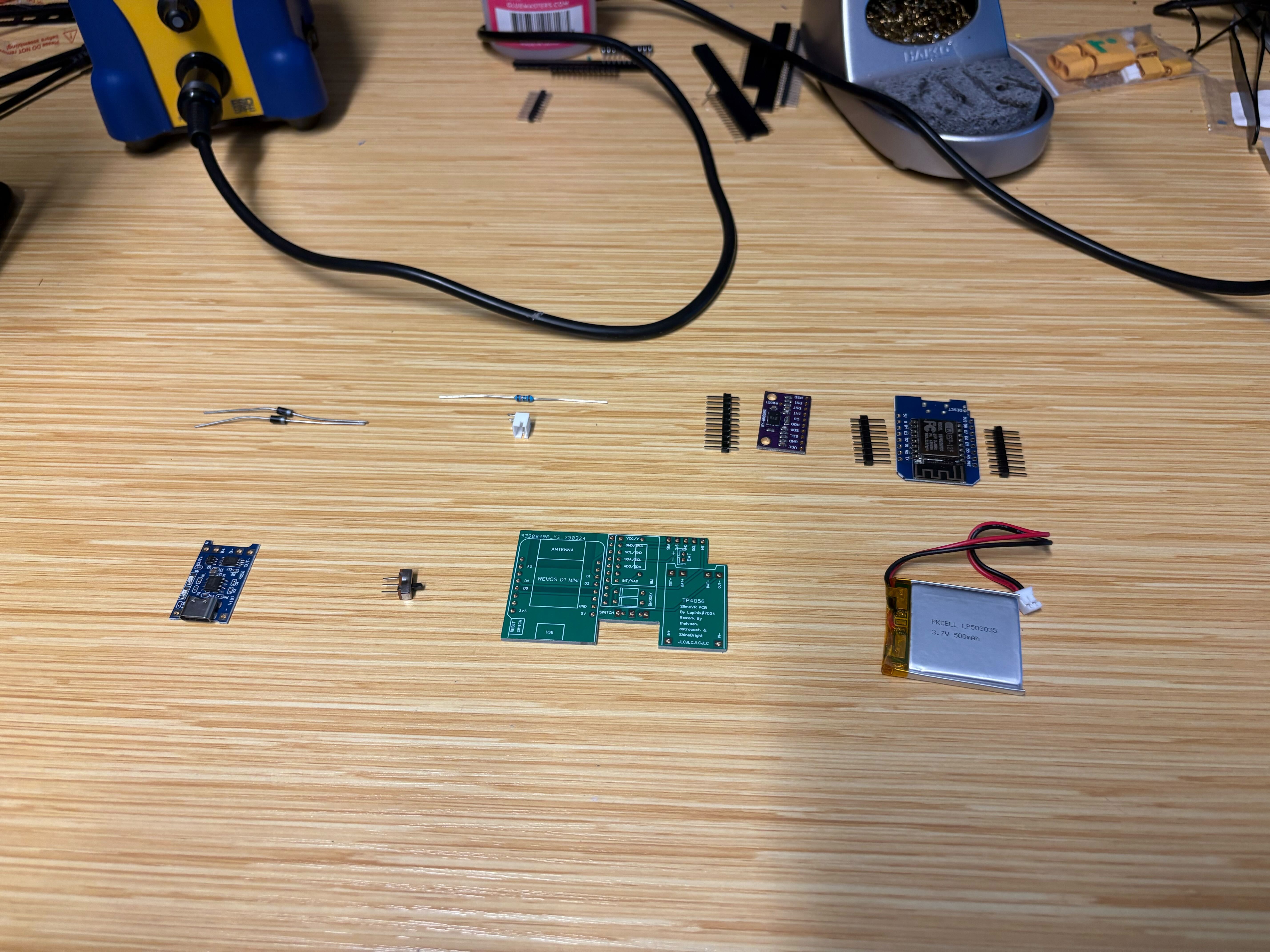
Overview of parts and PCB orientation before assembly.#
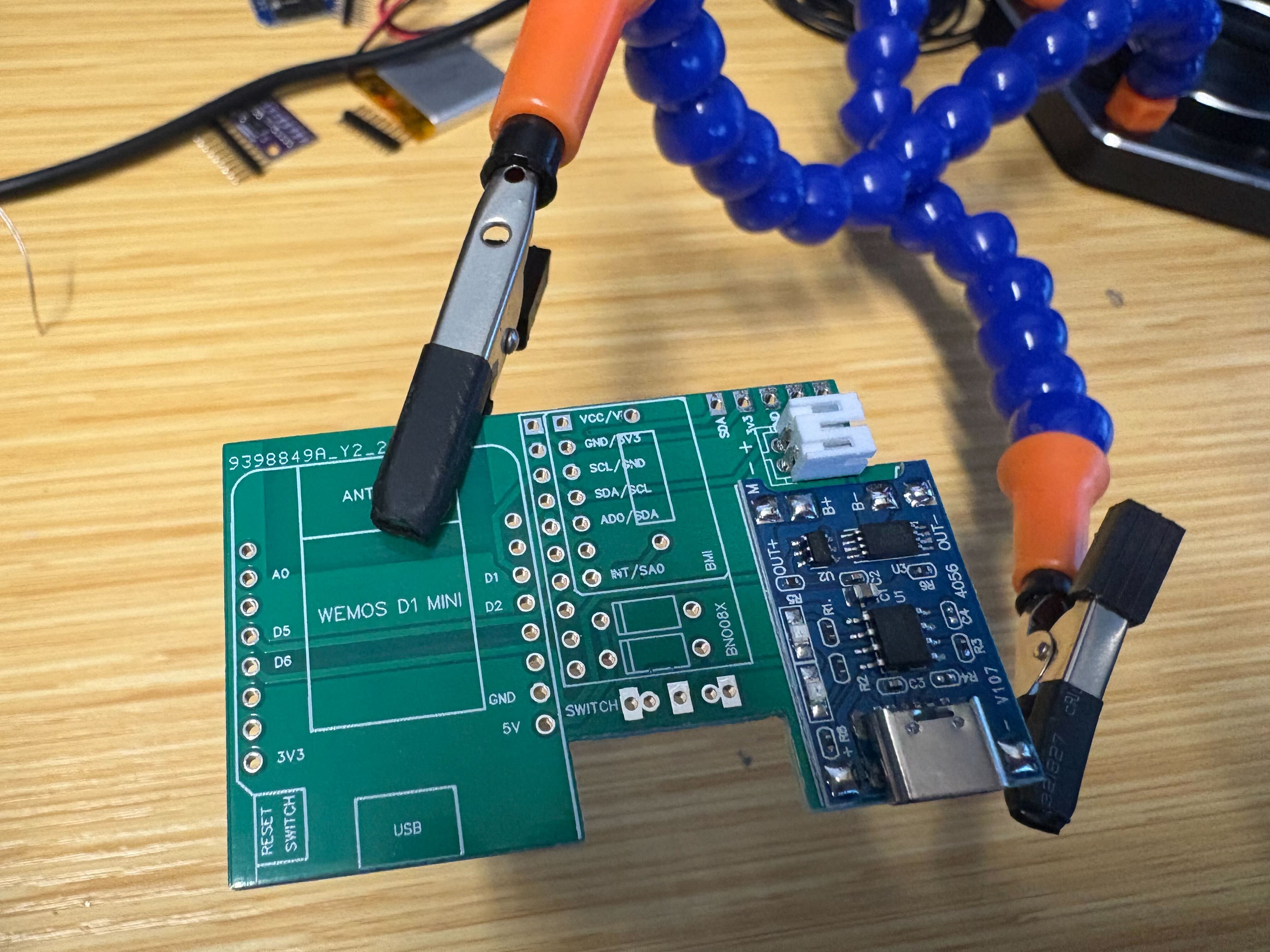
Charging board (TP4056)#
We start with the TP4056 charging board (sometimes called the BMS section in Hyperion build guides).
Seat the module so its holes line up with the PCB pads.
Tack one pin first, then reheat and nudge the board until all pads align, and solder the remaining pins.
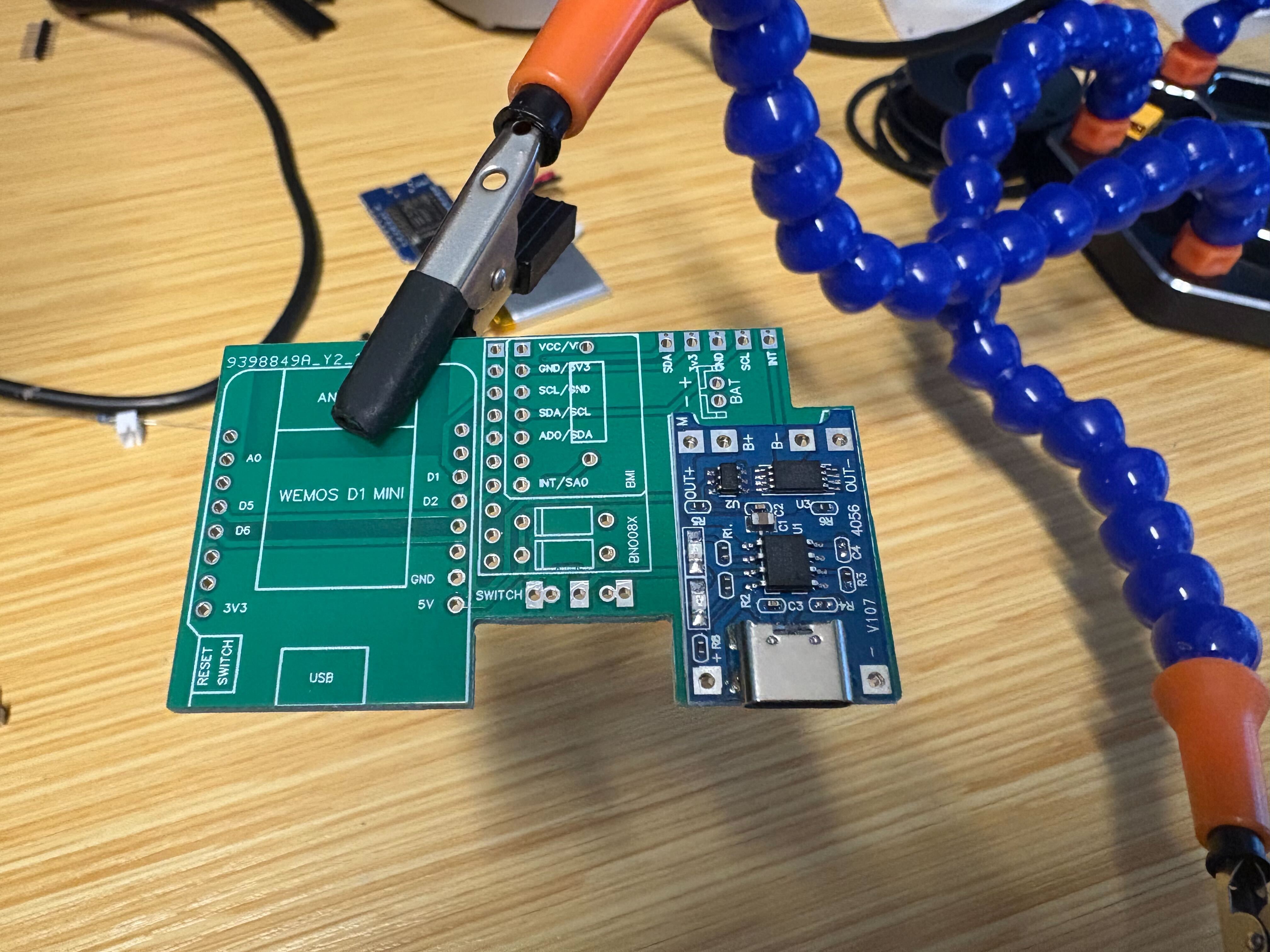
Align the charging module to the PCB footprint.#
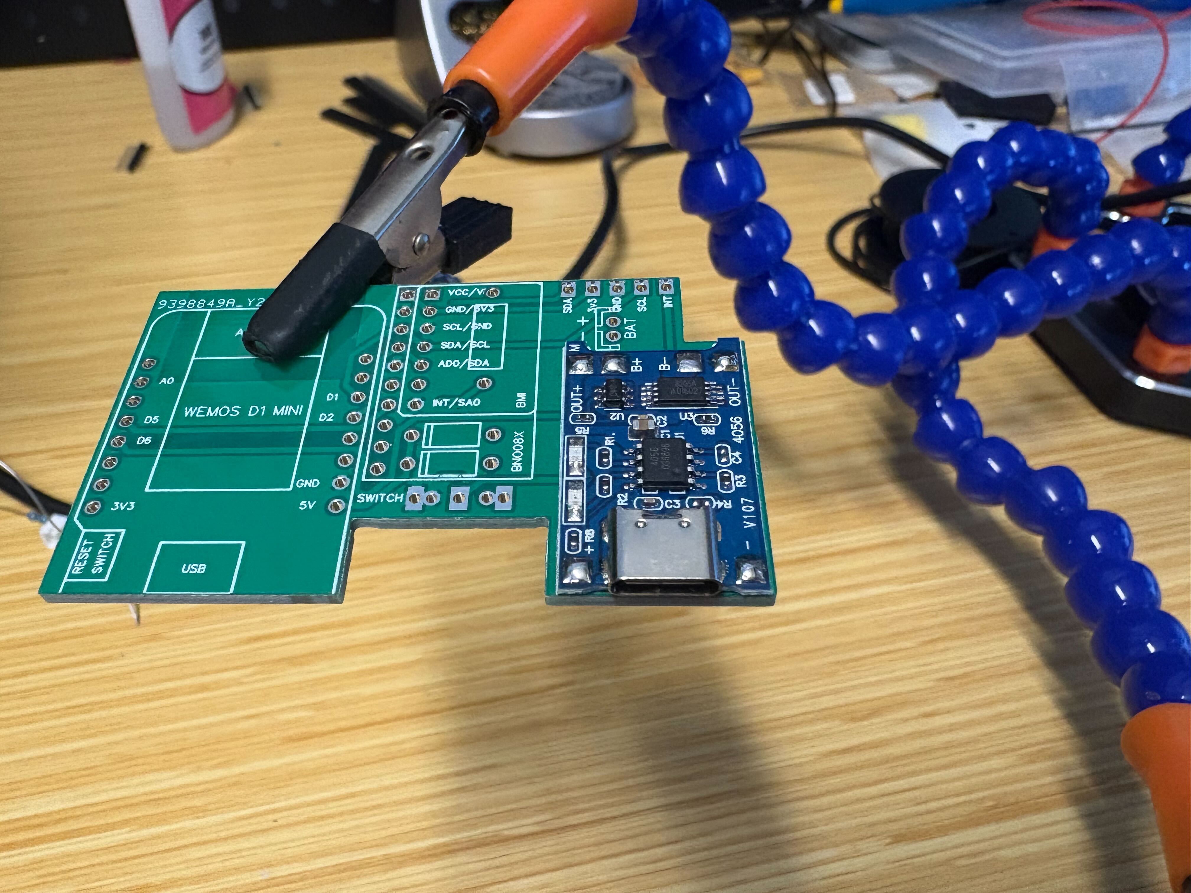
Tack one pin, align, then finish all joints.#
From underneath, through-holes should show proper fill.#
Battery connector (JST)#
Insert the through-hole JST into the battery power footprint. Keep it perpendicular to the board and aligned with the board edges, then solder from the underside.
JST seated square and soldered from below before taller parts go on.#
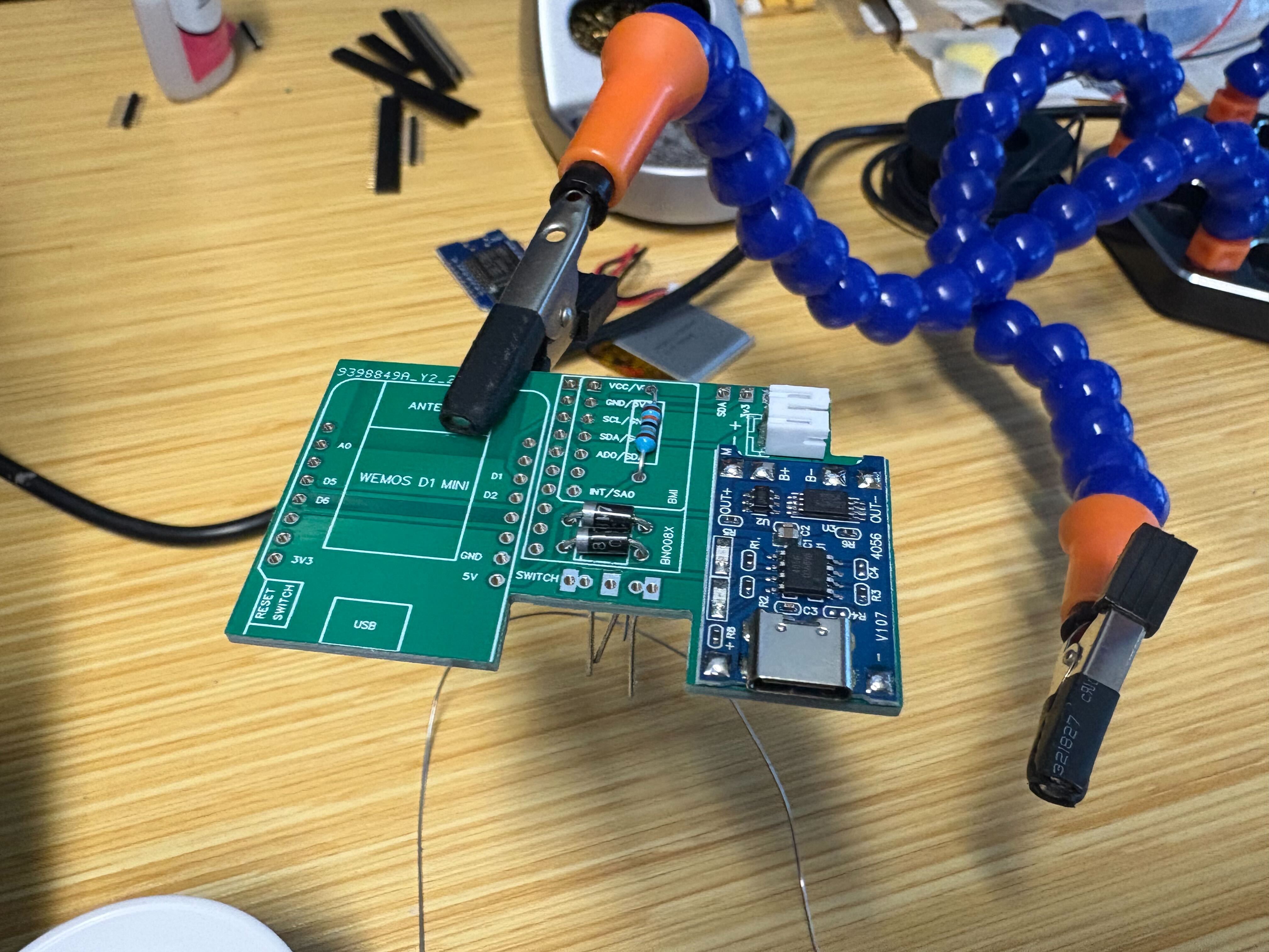
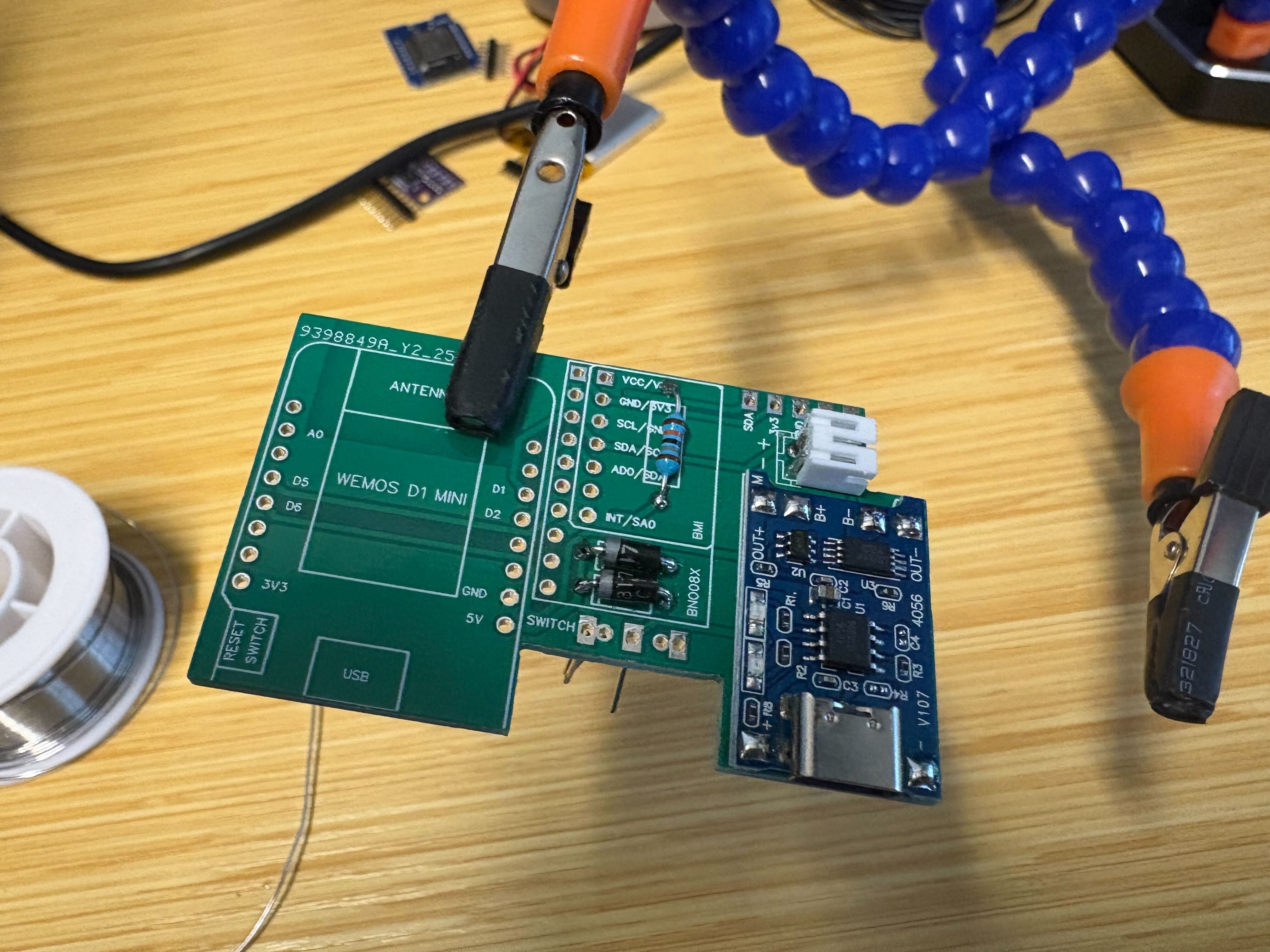
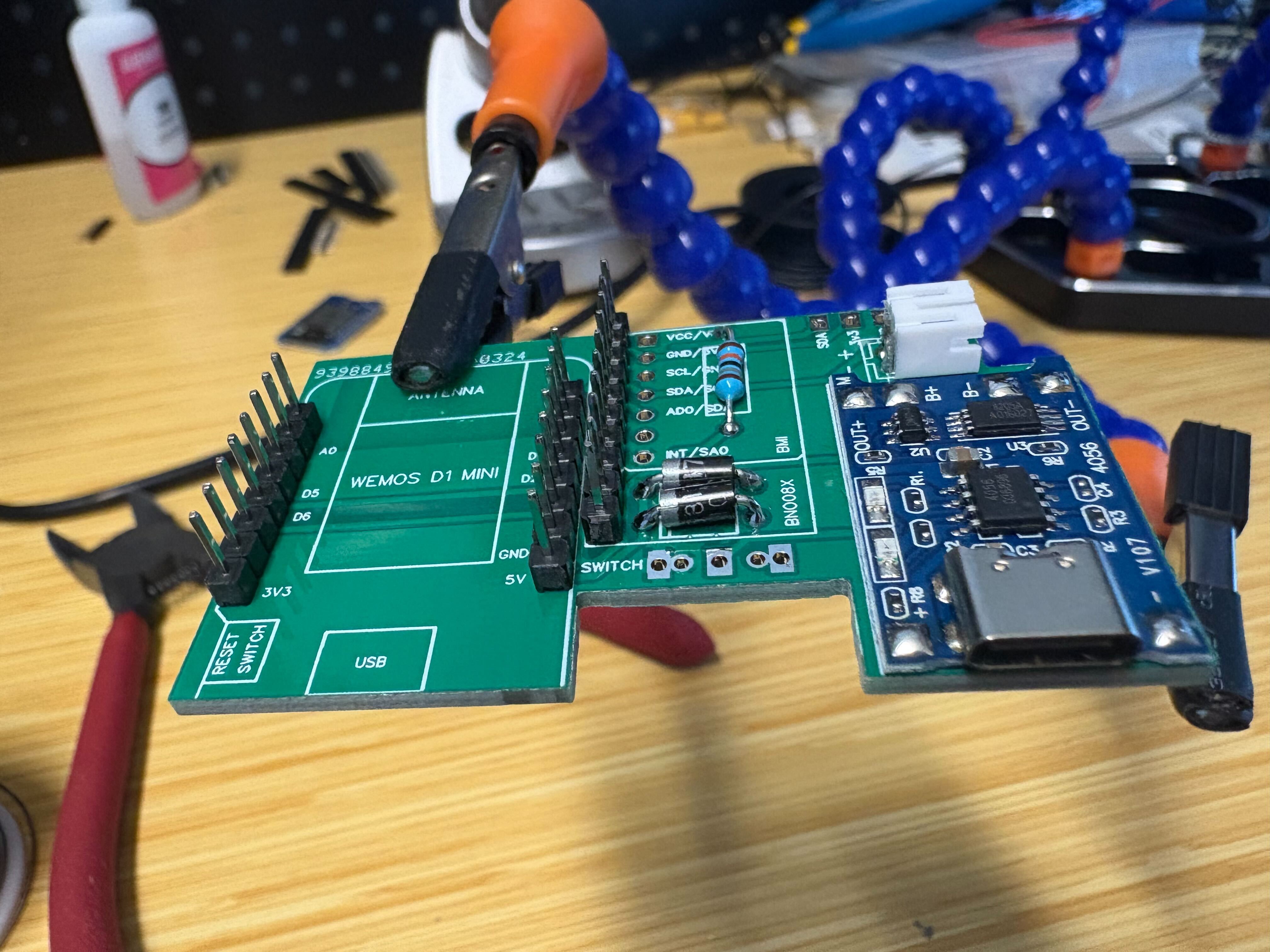
Resistor and diode#
Use a 180 kΩ resistor and the diode called out in the BOM. Match the diode polarity to the silkscreen, fit the passives flush, solder, and trim the leads.
Pin headers (IMU and ESP32 Wemos D1 Mini)#
For both the IMU and the ESP32 Wemos D1 Mini, point the long side of the pins up to make alignment easier.
BNO085 IMU#
Slide the BNO085 breakout onto its headers. Solder one pin first, check that the module sits almost parallel to the lower PCB, then finish the rest.
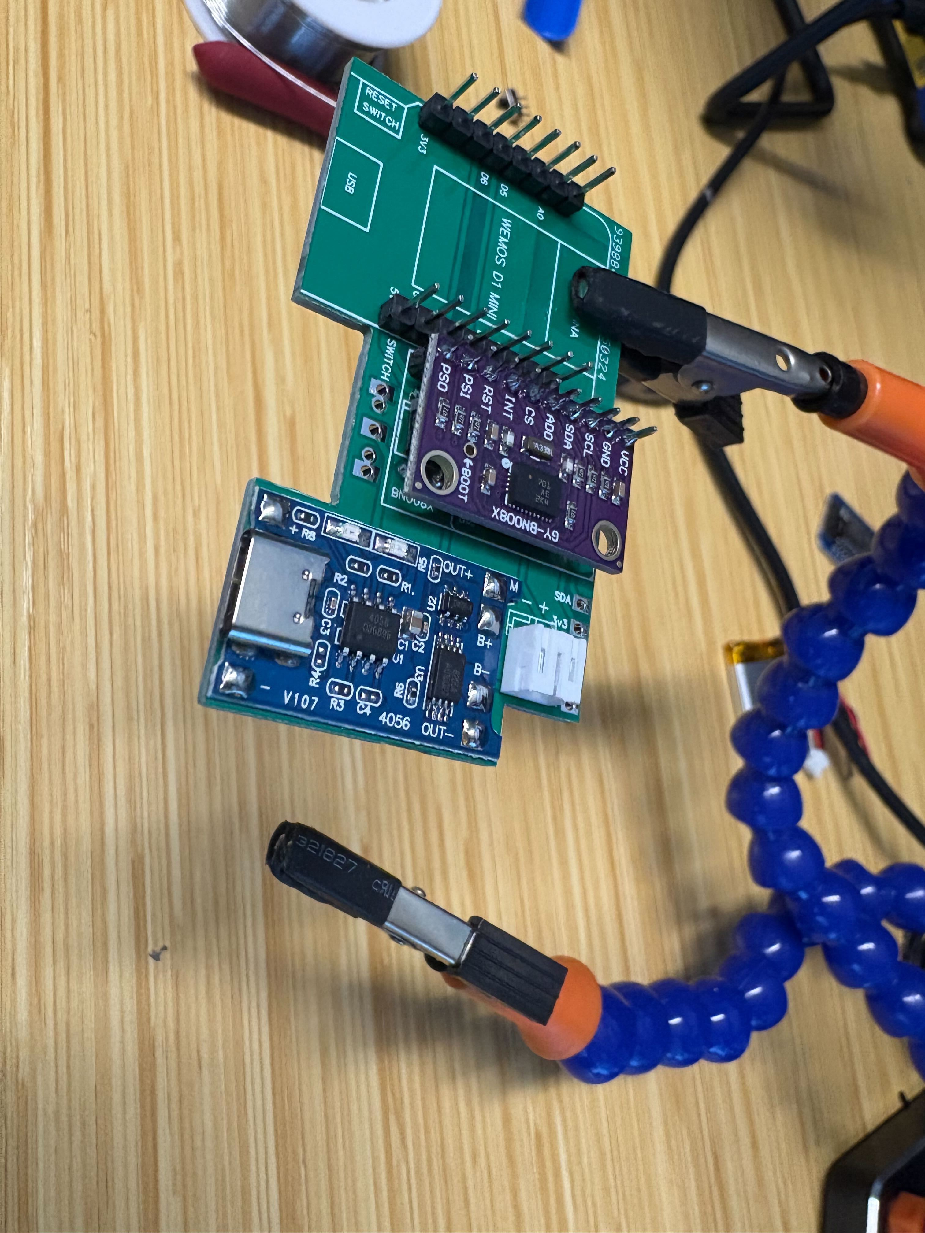
ESP32 (Wemos D1 Mini)#
Solder one pin on the D1 Mini, clip any over-long pins on top, then finish the remaining joints. Apply the same trick to the IMU if its headers stand tall after seating.
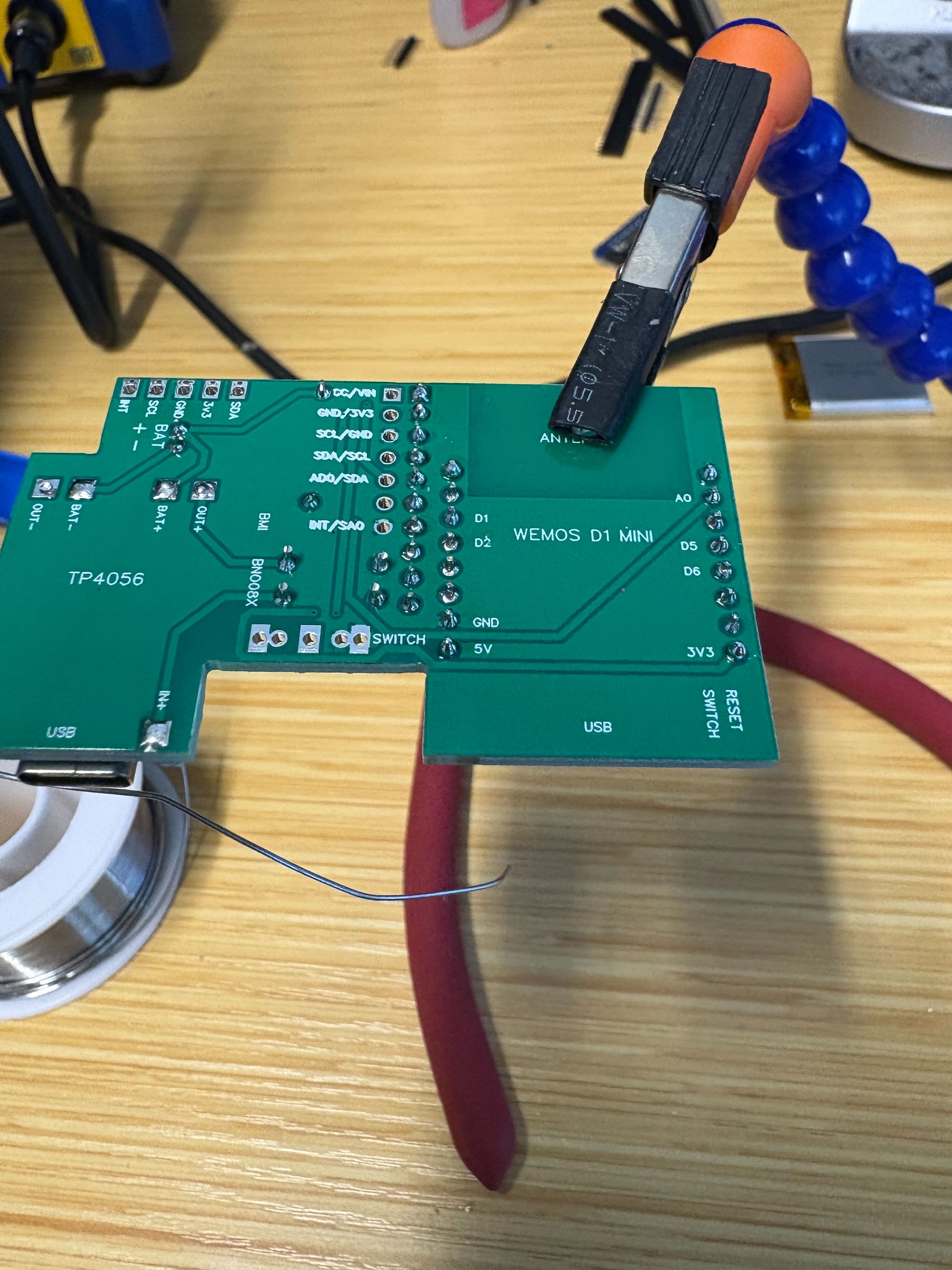
Connectivity test#
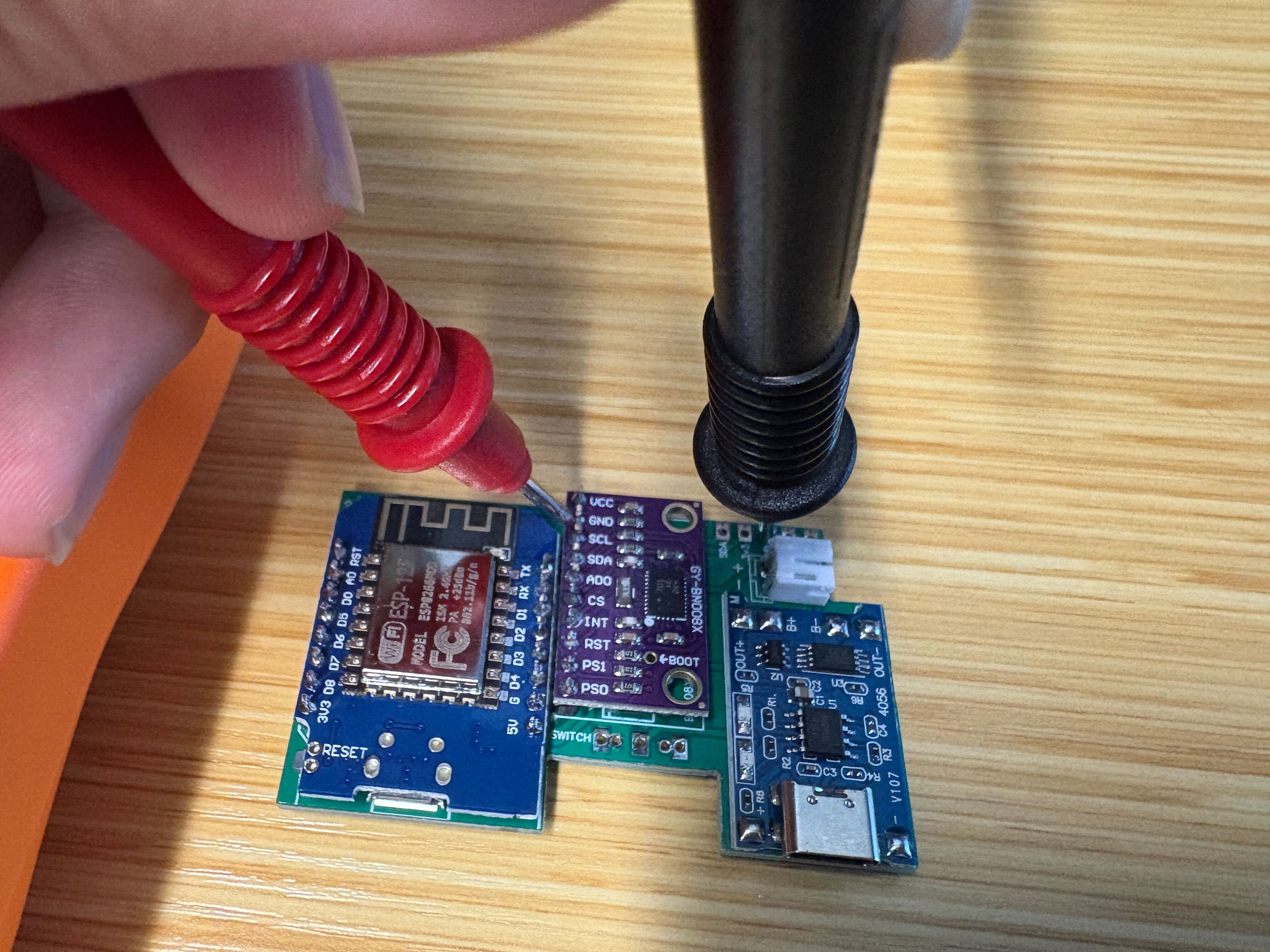
Continuity check with a multimeter (beep mode): verify VCC, GND, and other nets from the test points (or designated pads) so power and ground wiring matches the design before you apply battery power.#
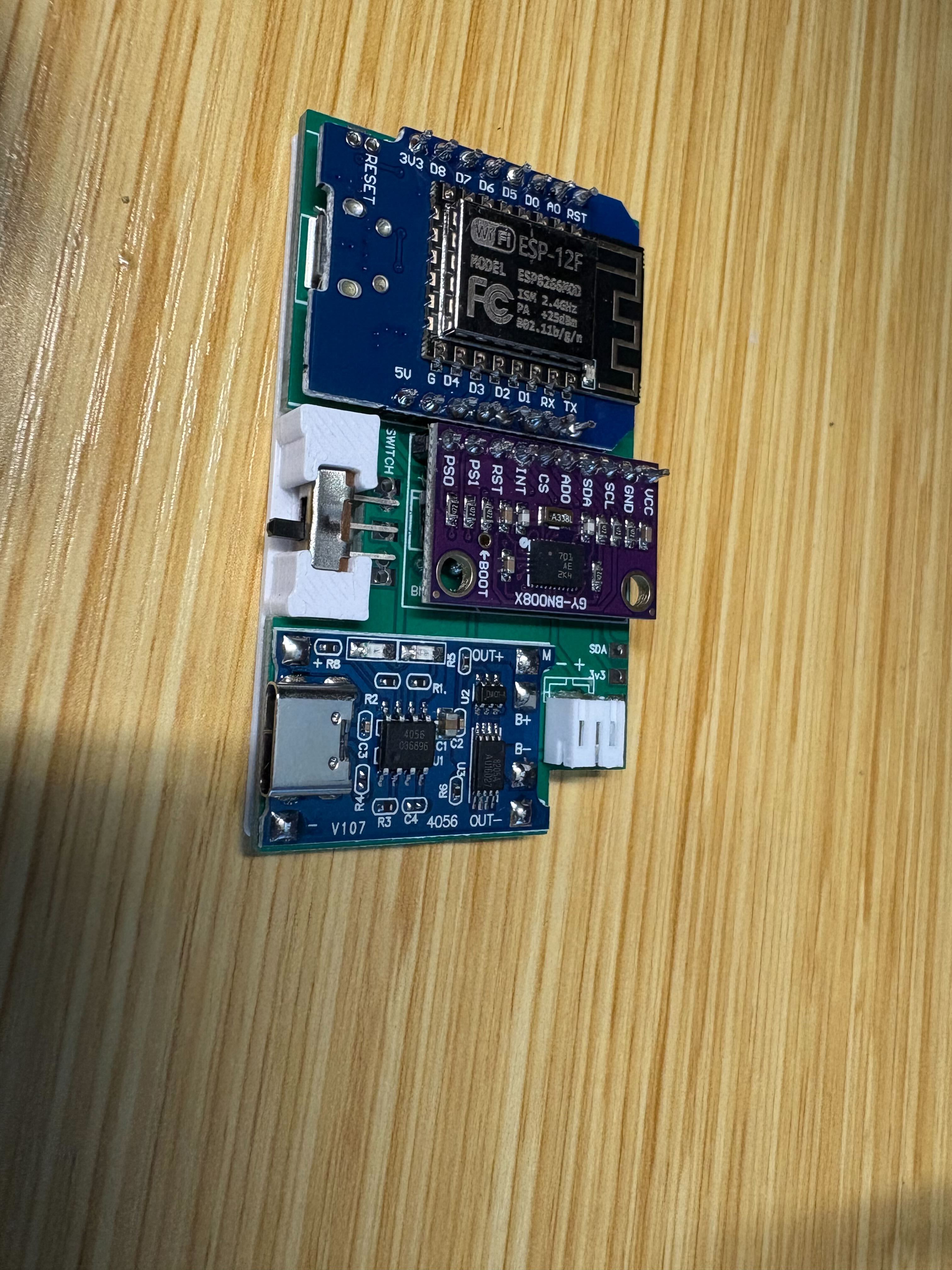
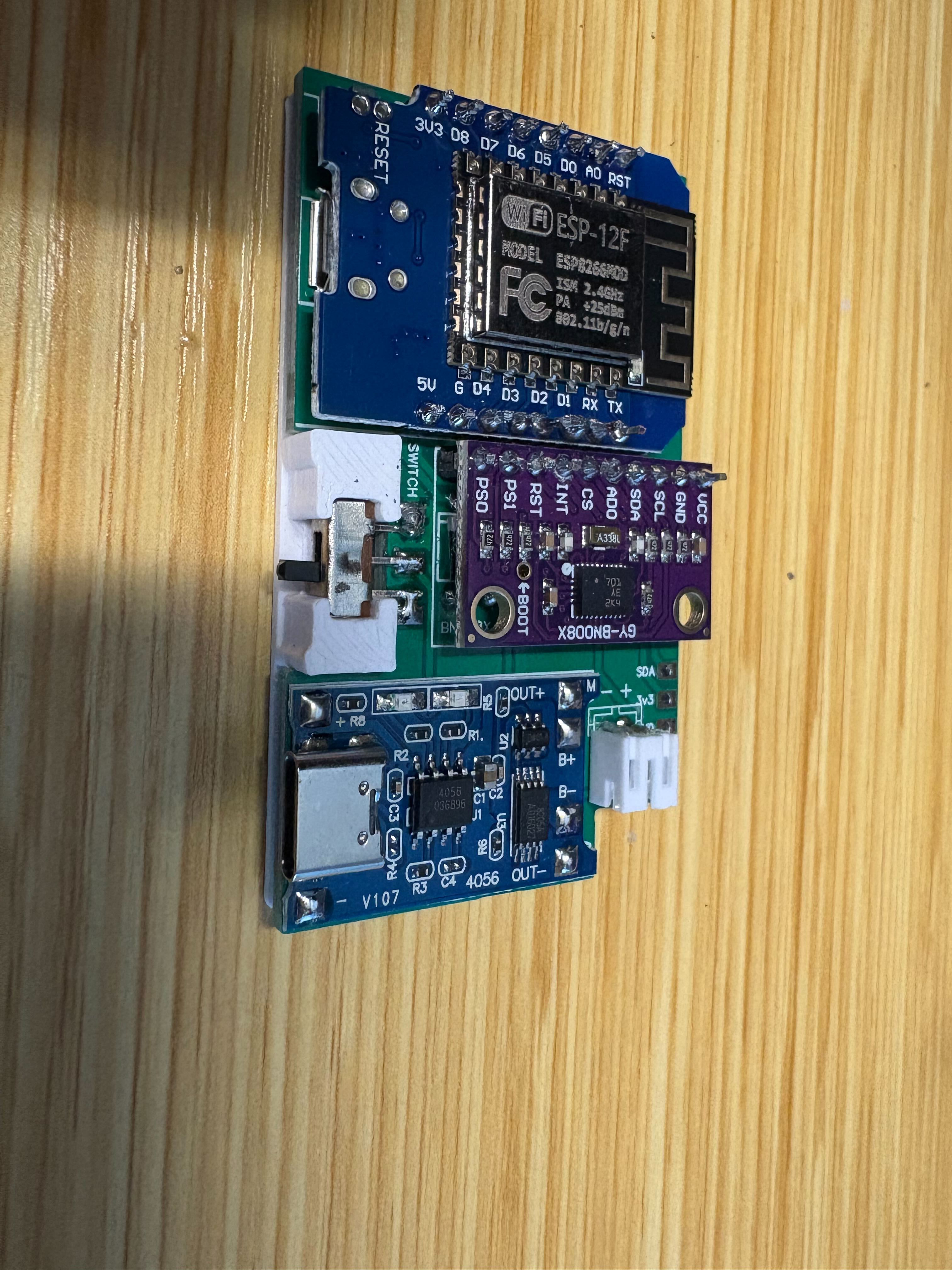
Power switch#
Use the printed switch tray to hold alignment. Press the switch down so its pins seat in the holes, then solder.
Power on#
Apply power once the continuity check passes. If the blue LED on the D1 Mini lights up, the board is ready for firmware flashing (this is power-on confirmation only, not a USB data test).
Enclosure and IMU stack#
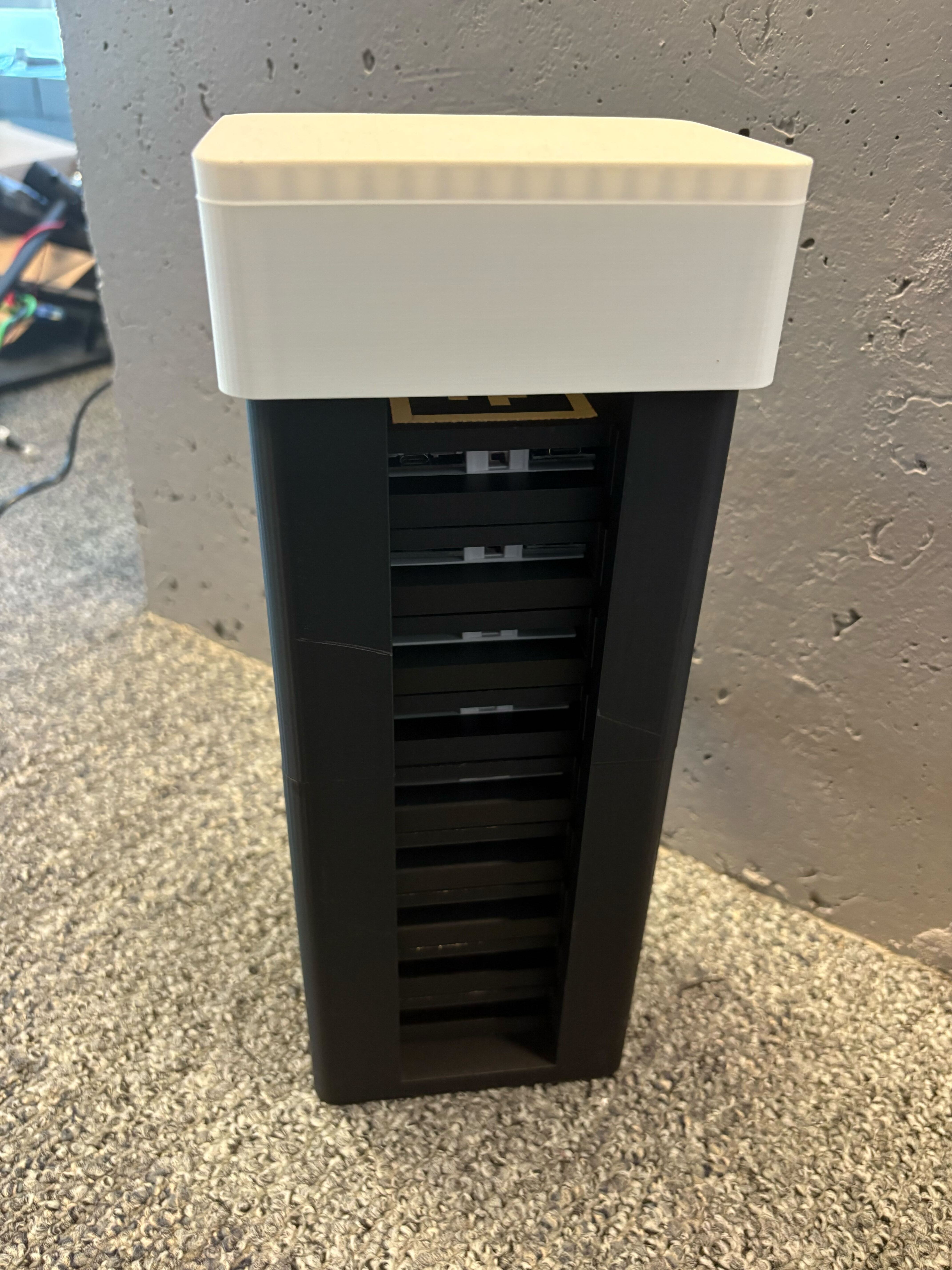
Press-fit the PCB stack into the printed shell, then route the straps through the provided loops and tighten until the tracker stays put without crushing the shell. The optional stack tower print helps keep all nine trackers organized for transport.
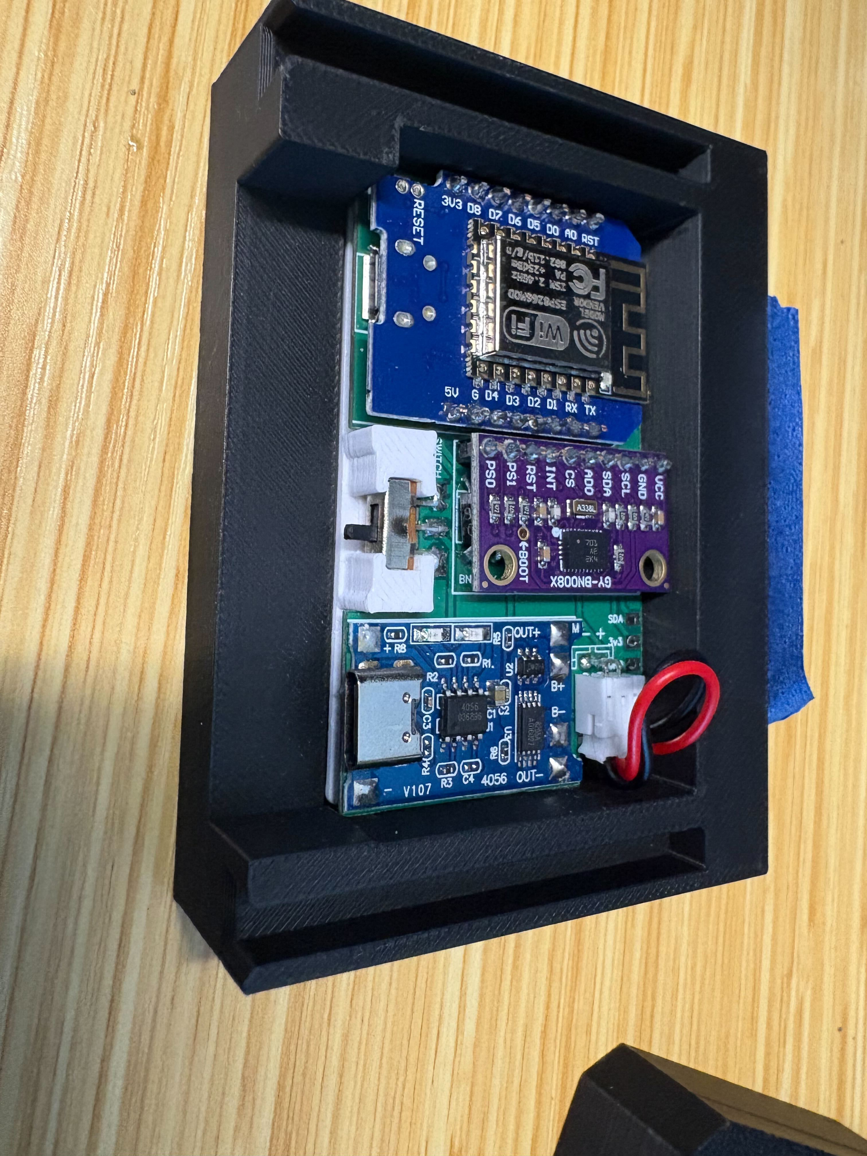
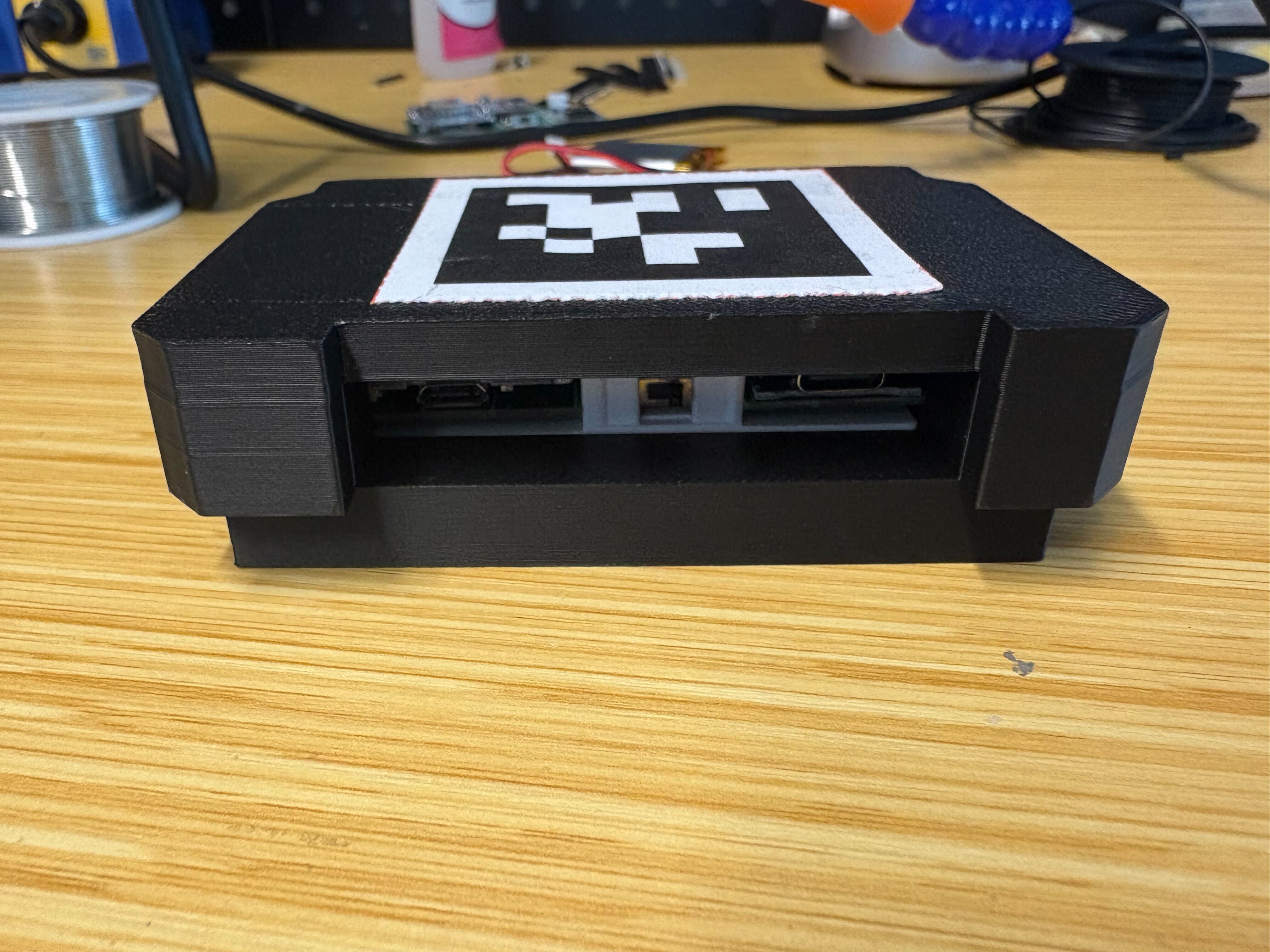
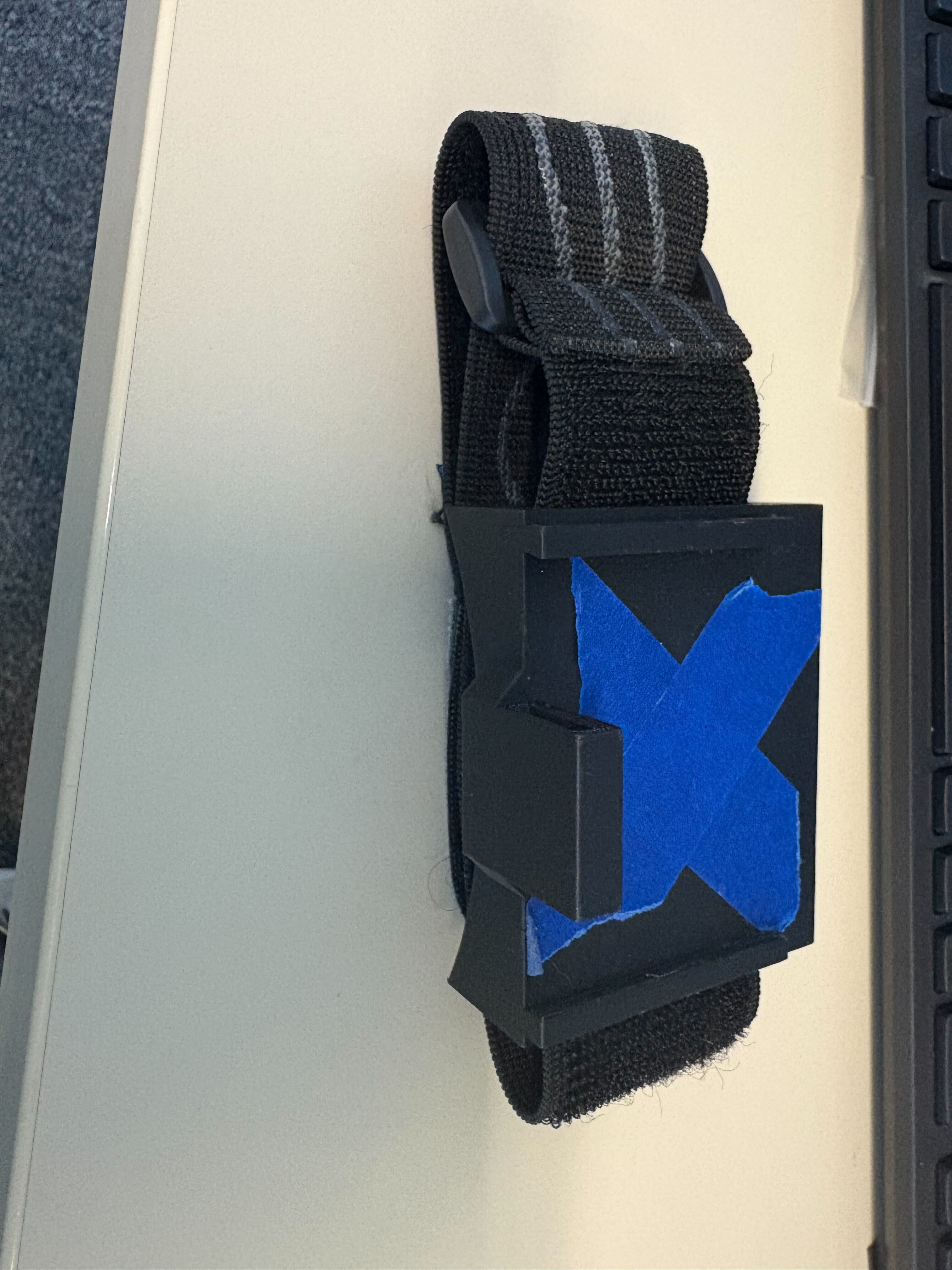
Rigid case closure and strap routing.#
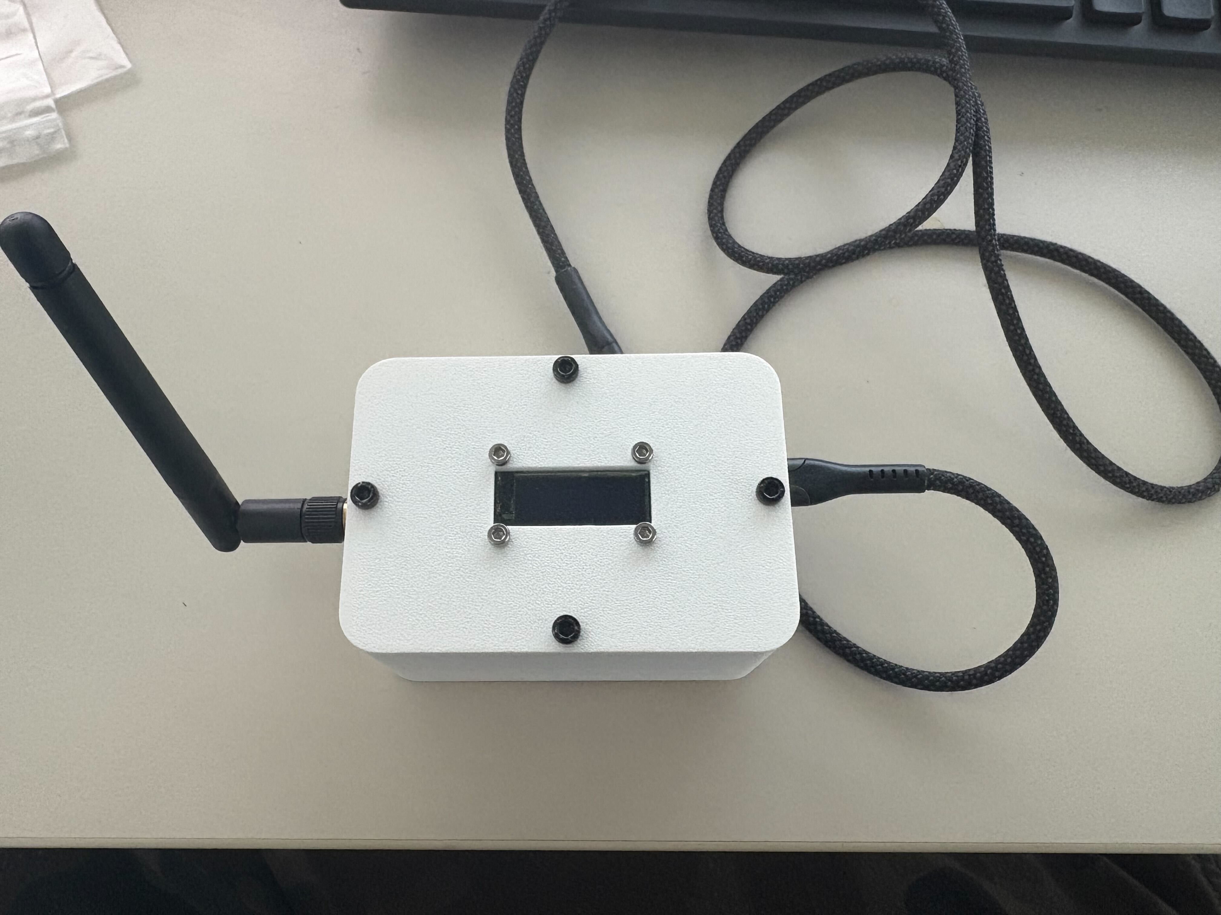
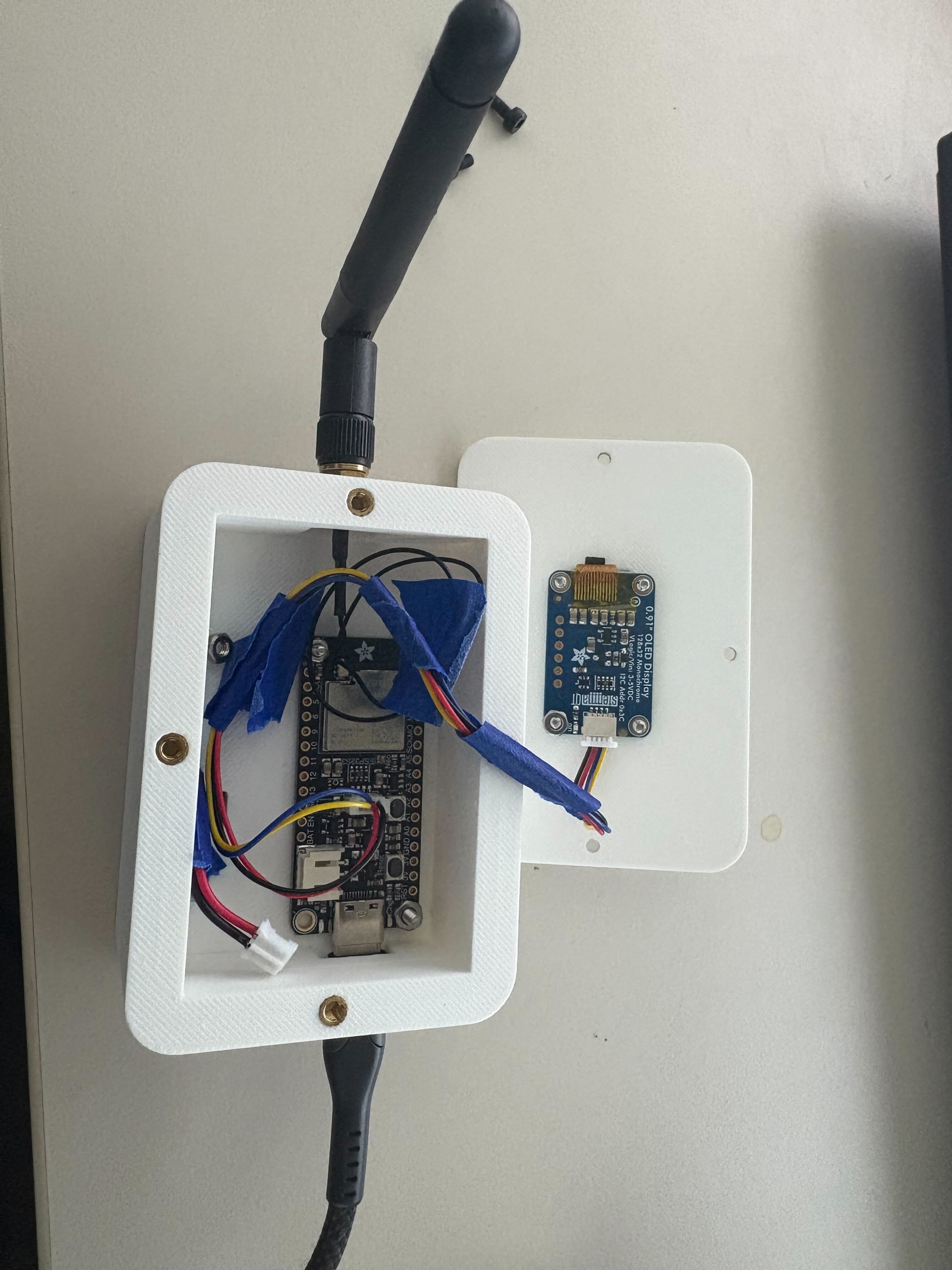
Receiver unit#
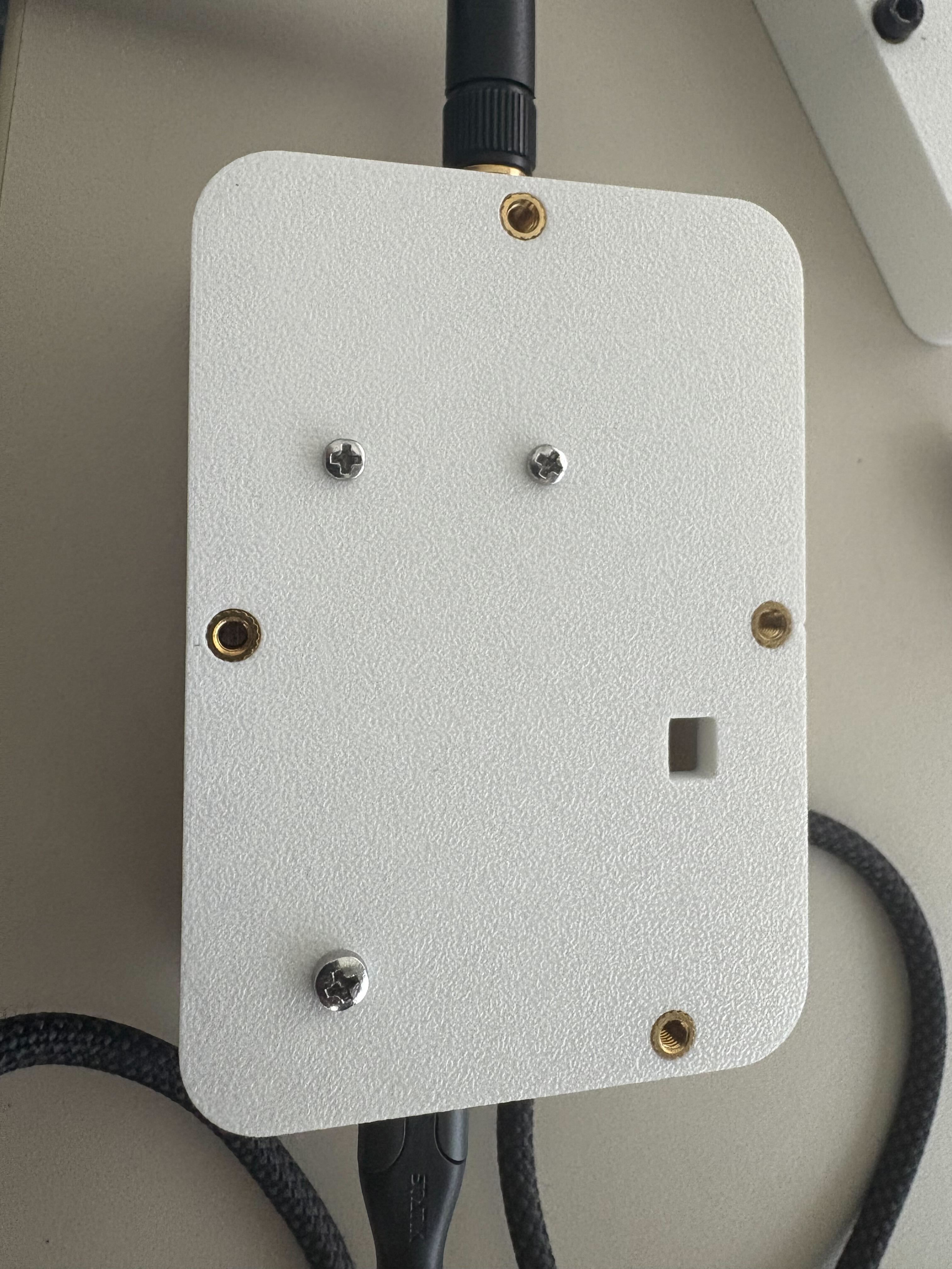
The receiver is an ESP32-S3 Feather that collects tracker packets over ESP-NOW (2.4 GHz, external antenna) and shows per-tracker status on an I²C OLED. M3 threaded inserts hold the printed enclosure halves together, and a single USB-C cable links the receiver to the capture workstation. For the BOM see Components; for firmware flashing see Software (firmware and host tools).
Attaching AprilTags#
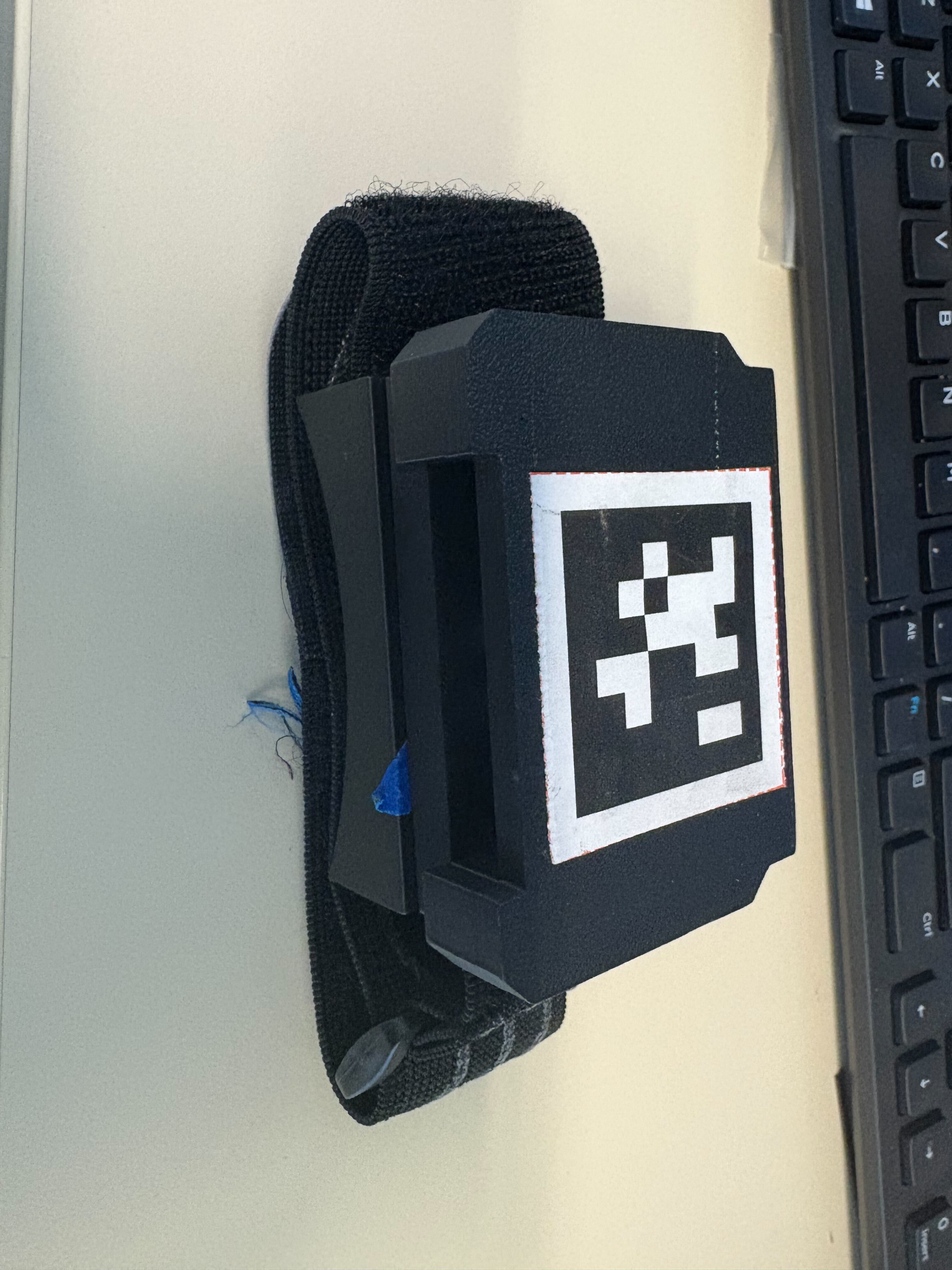
Each tracker carries a printed Tag36h11 AprilTag (42 mm outer square) rigidly bonded to the flat face of its case—use a flat insert or printed pocket, not a loose sticker, so the tag cannot flex or peel during motion. Print matte to reduce room-light glare and keep clothing or straps clear of the tag during capture.
Orientation. The tag’s +Y axis must point toward the charging port (green axis in the photo below). The calibration pipeline assumes this; inconsistent orientation will produce wrong sensor-to-bone offsets. Tag IDs follow the mapping in Components.
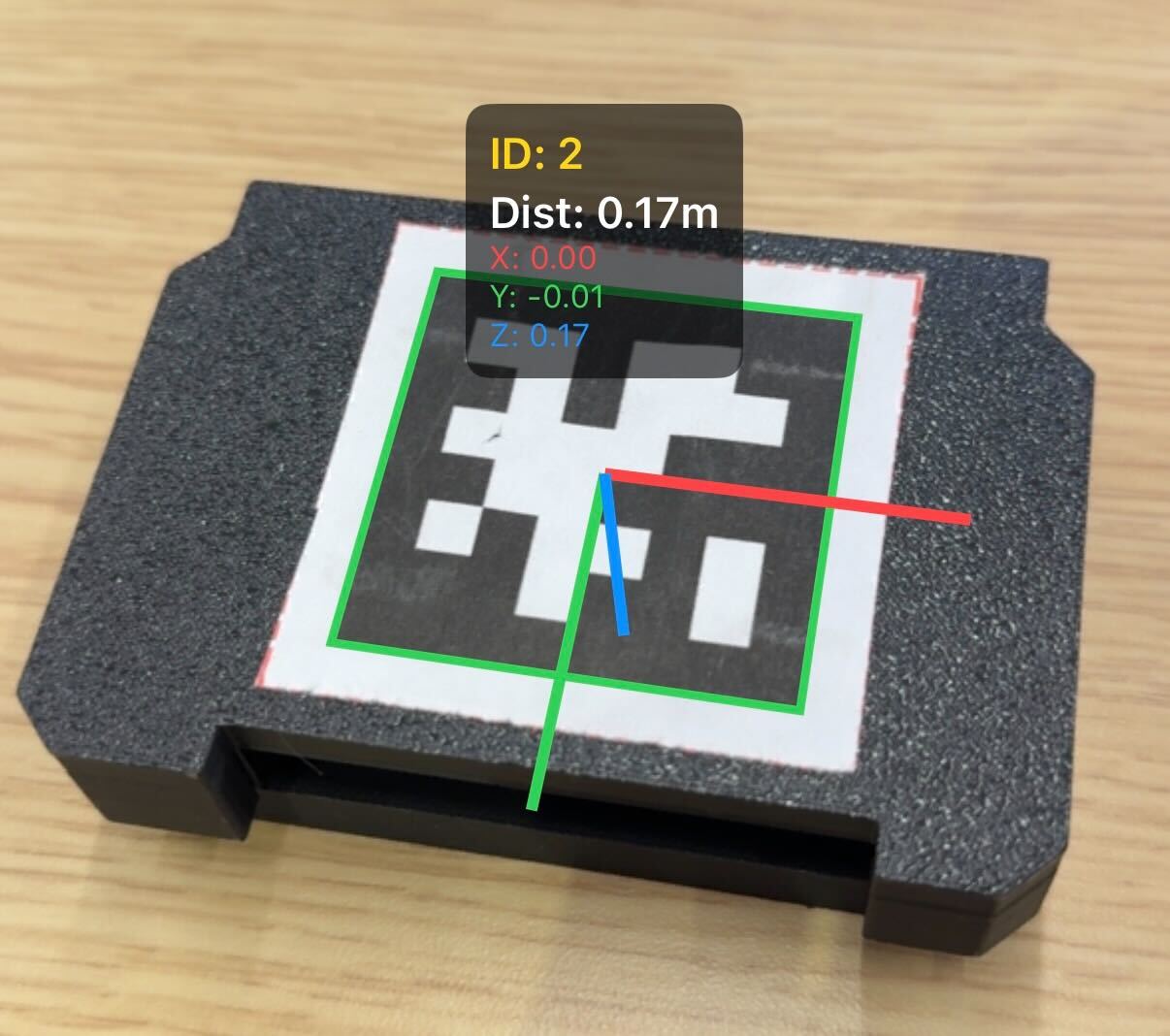
AprilTag mounted on a tracker with axis overlay. The green (+Y) axis points toward the charging port.#
Next step#
With soldering and the enclosure complete, continue with firmware flashing and host Python setup in Software (firmware and host tools).